|
|
|
Suzuki Swift GTi – Megasquirt Installation
By Sebastian Giroldi – caaarlo@hotmail.com
San Juan – Argentina.
Rev 1.4 Sept. 16, 2006.
The purpose of this text is to serve as a guide for those who already have a megasquirt 1 (68HC908 controller) with the V2.2 or V3 board, and have tested them to communicate and work. The reader should already understand the basic operation of Megatune. For basic megasquirt and megatune reading, please visit the MS website ar www.megasquirt.info or the MS forums at www.msefi.com where assembly and testing information can be found.
1. Introduction.
Since the release of the MK2 Suzuki Swift GTi in 1989, I have always dreamt of this car. Finally, in October 1996, my dream came true and could buy a brand new MK3 GTi. Since then, it has experienced many changes like wheels, tires, suspension, as well as some internal modifications. During the past years it has experienced some major mechanical changes like cams, head work and a custom exhaust. Due to the last changes, it was necessary to match the ECU program to the new internals, so I purchased the only chip that I thought could work for my car, the expensive but promising ssgti.com MK3 Stage 2 chip. I expected a night and day difference, but the only difference I noticed was the 8600 RPM fuel cut. Very disappointing, isn’t it ? It suffered from the same lack of fuel as the stock chip between 6500 and 8600 RPM. Furthermore, the ssgti chip had the same idle speed as stock: 850 RPM, leading the new engine with increased overlap to stall from time to time. The crappy chip was a waste of money, and I decided to look for something better and definitive, knowing that a turbo project was in sight.
After many months reading all the swift forums, with several reviews of aftermarket chips, computers and piggybacks, I found the Megasquirt to offer the most convenient cost/benefit ratio, with the only drawback of being an experimental do-it-yourself and use-at-your-own-risk computer. But hey, I get on well with electronics, so I decided to go and give it a try. The basic kit arrived about 10 days after placing the order by internet, then spent an extra week getting the rest of the materials, and finally could finish my V2.2 megasquirt. But (there’s always a BUT) it was not that easy. The chip came with the original Megasquirt code, which was good for fuel management only. Soon I realized that I needed Megasquirt and Spark Extra code (MSnS-E), so I downloaded the code from internet and re-programmed the chip. And, once again, I needed more stuff, because the new MSnS-E code was very flexible, but not enough to decode the Swift’s reluctor wheel inside the distributor. Then I got very discouraged, up to a point when I was about to modify the stock reluctor wheel with a grinder to make it ‘readable’, getting to a point of no return and erasing the remote possibility of getting back to stock some distant day. After some sleepless nights and a few PMs with Baldur Gislason, I could find my way to the solution, making a custom code able to decode the swift’s reluctor wheel. Only took me a couple of afternoons to understand the standard code and figure out how the original wheel decoder worked. It wasn’t difficult, but the lack of practice in programming microcontrollers delayed for some days the final version of the so expected ‘custom wheel decoder’. The rest is explained in the rest of this document, which, I hope you will find useful.
2. Firmware changes.
Firmware you said? Yes, firmware or ‘code’ is the program stored in the megasquirt, it is equivalent to the program and tables stored in our stock 27c128 or 27c256 EPROM chip. The brain of the megasquirt is a Motorola 68HC908 microcontroller, containing the processor, RAM, flash ROM, A/D converters, timers, and many others in a single chip. The program or firmware is stored in the flash ROM, which is similar to a memory stick, a multimedia card or a pen drive (all these devices are flash memories), and it must be updated to a different code able to ‘read’ or decode the reluctor wheel inside the distributor. This wheel is very important for the management system because it is the way the ECU knows the crankshaft position and the engine speed. So, If the ECU can’t get the message from the reluctor wheel, then it simply won’t work, or will think that the engine is stopped.
Once you have your megasquirt working and have passed the communications test (this is explained in www.megasquirt.info) you can download the custom code to your computer and upload it to the megasquirt. For now, the code is based on MSnS-E 25m1 with some changes made to the wheel decoder, Idle solenoid control and thermo-sensors (it will ONLY work with stock Suzuki sensor type, stock idle solenoid and stock reluctor wheel)
IMPORTANT: This code will only work with Suzuki coolant sensor and a similar type for the Intake air sensor.
Follow these steps (also explained HERE)
Congratulations! You have just re-flashed the new code into your Motorola processor,and it will let the MS interact with some sensors and actuators found in the G13B.
3. Software changes.
I am using Megatune 2.25b602 beta, but any later release should work as long as the msns-extra.ini file is replaced by the correct one (explained below). Megatune can be downloaded from HERE . Sometimes it will ask for a couple of dll libraries that can be downloaded from the internet, but this is explained in the MS website and forums.
All versions of megatune are set up to work with the original B&G 3.0 code and GM type temperature sensors, so we need to update some files to match our custom code and Suzuki sensors. The first thing to do is to set up Megatune to MSnS-E mode. When you install Megatune, a directory like c:\Program Files\Megasquirt\car1\MtCfg will be created. In there you'll find a file settings.ini, open this up in Notepad and edit it so it looks like the following:
#unset DFI ; David Hooke's Ducati FI
#unset DUAL_TABLE ; Guy Hill and Eric Fahlgren's Dual Table variant
#unset MSNEDIS ; James Murray and Dave Hayne's MSnEDIS ignition variant
#unset MSNS ; Magnus Bjelk's MSnS ignition variant
#set MSNS_EXTRA ; James Murray and Phil
Ringwood's MSnS Extensions
#unset MS_ECU ; Robert Hiebert's EEC-IV replacement code
#unset MS_I ; Bowling and Grippo MegaSquirt
#unset MS_II ; Bowling and Grippo MegaSquirt-II
#unset MSpark ; Tom Hafner's MegaSpark variant
#unset PIC_SQUIRT ; PIC squirt
The next step involves the sensors. You have downloaded the custom code and extracted to your hard disk. The directory \25mx\source\ contains many files with the .inc extension and also the file msns-extra.ini. Copy them to your megatune directory at
C:\Program Files\MegaSquirt\MegaTune2.25bXXX\mtCfg
Congratulations!. Your Megatune is now ready to interact with the custom MSnS-E code.
4. Hardware Changes.
4.1. Bias Resistors.
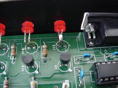
If you are running the custom code, with Suzuki temperature sensors, then you must replace bias resistors. There are two 2490 ohm or 2.49K resistors, labeled R4 and R7 on both V2.2 and V3 boards. These resistors must be replaced by similar type, but 2200 ohm or 2.2Kohm.
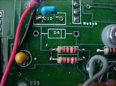
The two 2.2K resistors
ready to work with the
stock temperature sensors.
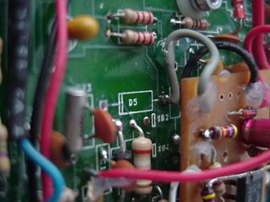
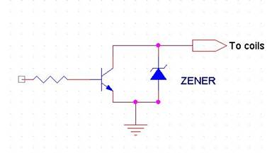
4.2. Zero crossing detector.
The zero crossing detector basically conditions the noisy analog signal coming from the reluctor pickup inside the distributor and makes it readable by the microcontroller. It is the weak link in any VR based megasquirt installation, and it sometimes can get tricky to make it work correctly due to the noisy nature of the VR signal.
If you happen to have the V3 board, it already has one and you can skip this section, but I can’t tell how it performs. However, the V2.2 board does require a zero crossing detector along with some other circuit mods, because we are no longer detecting a spark signal for synchronizing the processor, but a VR signal instead. So, the spark detection circuitry must be disabled and it can be done by removing D5 (actually you can also remove R10, D8 and C12, but D5 will suffice). Also remove C11 and replace it with a 1nF ceramic capacitor.
Once the mods are complete, a zero crossing detector should be connected to the board. There are many circuits that can work, but so far, there is one circuit that delivered the best results in my car. It is based in the rugged LM1815 from National Semiconductors, with a resistive divider at the input, to condition the signal from the magnetic pickup.
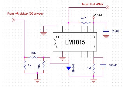
The circuit should be connected as follows:
The input of the detector
connected to the VR input pin.
(Anode of the already removed D5)
The output goes connected to pin 6
of the 4N25 optocoupler.
The only connections remaining are ground and +5Volts, well there are many points over the board where we can find those voltages. I took 5 volts from R11 and ground from the anode of D3.
4.3. Drivers for Idle solenoid and fuel pump.
The swift’s idle solenoid has a 25 ohm coil. To ensure that the megasquirt will feed the coil with the necessary current and that it will not inject noise to the 12 volt line, the following mods are necessary.
For V2.2 Board:
Replace R16 (1K) with a 470 ohms resistor (same type, ¼ W).
Replace Q5 (2n2222) with a ZTX450 or BC639 (check pinout)
Optional:
Remove D9 and D7. Then, for each of the two drivers, Solder a 22V – 1Watt zener diode with cathode connected to collector of transistor and anode connected to emitter. On a diode, the cathode is denoted by a strip painted on its body.
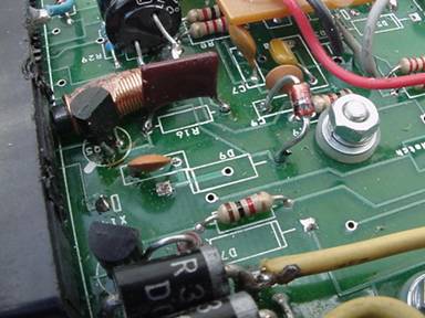
Idle solenoid driver. D9 was removed,
R16 was replaced by a 470 ohms one,
the transistor was replaced by a BC639
and a zener connected between collector
and ground (emitter)
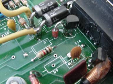
Fuel pump driver. D7 removed and
zener connected between collector
and ground (emitter)
This is the new driver circuit
with diodes removed and zener
connected between collector
and emitter.
For V3 Board:
Replace R19 with a 470 ohms resistor (same type, ¼ W)
Replace R39 with a piece of wire (jumper)
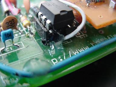
4.4. Ignitor output.
The spark is generated by sending a signal to the ignitor. I use LED 17 for this task (on V3 it is LED14). Replace the led with a jumper, or short circuit its legs with solder. Then route a wire from this jumper to one of the spare outputs at the DB37 connector. I used pin 31 (X14 for V2.2, or IAC2B for V3), but it is more advisable to use PIN36 (unused pin for the V2.2, or IGN spare pad for V3). Use this output to command the igniter. On the V3 board there is an option to use the internal IGBT module instead of the stock igniter, but I can’t tell the results. So far, the stock coil and igniter has performed very well up to 9000 RPM.
LED 17 with its legs soldered.
A cable is routed from any of its
Legs to a Spare pin at the DB37.
This pin will then connect to the
Ignitor.
4.5. Filtering of Fly-back switching noise.
Note: If you are using high impedance or saturated injectors, then skip this section.
The fly-back board becomes necessary whenever low impedance or peak and hold injectors are used, and it basically switches them on and off at very high speeds. The Megasquirt seems to have a design problem because this switching noise somehow gets horribly coupled into the 12 volt lines creating high amplitude noise that can reset our megasquirt.
To overcome this problem, some filters must be placed and some tracks must be cut.
Follow these steps:
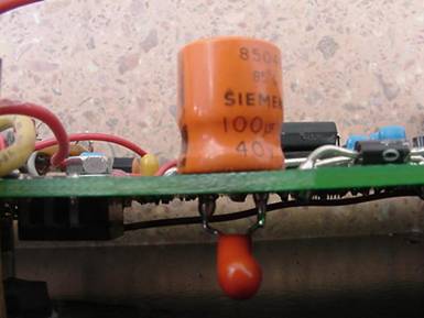
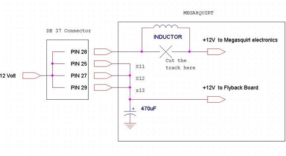
1- Place a 100uF x 25 volts electrolytic condenser in parallel with C15 tantalum condenser. (C16 for V3 board)
2- Besides pin 28 (DB37) for feeding 12 volts, it is advisable to connect other three spare pins of the DB37 connector to feed the fly-back board with 12 Volts and leave pin 28 for feeding the rest of the electronics. This is necessary due to the increased current injected by the fly-back to the 12 volt line. I used X11, X12 and X13.
3- Place a 470 uF x 25 volts electrolytic condenser between +12 volt auxiliary pins to ground. The cap should be connected as close as possible to the DB37 connector. FEED THE FLY-BACK BOARD FROM THIS POINT.
4- (OPTIONAL) Identify the track that connects the regulator stage (LM2937, condensers and diodes) to +12volt at pin 28 of DB37. Cut this track with a knife or sharp blade. Now you have two tracks. Connect the two tracks with a 5 micro Henry or larger inductor (in other words, place the inductor in series between the regulator stage and the 12 volt line). I made my inductor from a cylindrical ferrite core and 15 turns of 0.3mm copper wire. This would suffice.
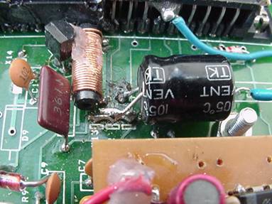
The image shows X11, X12 and X13
connected together and the 470uF cap.
Next to it, the inductor in series with the
12 volt line to the regulator stage.
For V3 board users, I guess it is difficult to feed the fly-back and MS with different lines due to the multilayer board construction. If so, then only reinforce 12 volt line with three spare pins (IAC1A, IAC1B and IAC2A) and connect them all together in order to have four pins to feed the MS with 12 volts, along with the two electrolytic condensers. I am sorry, but I don’t have a V3 board to experiment with.
These are the necessary mods
to provide the MS with a more
acceptable noise filtering.
The 100uF cap is not shown,
But it should be connected in
Parallel with C15(V2.2) or
C16 (V3)
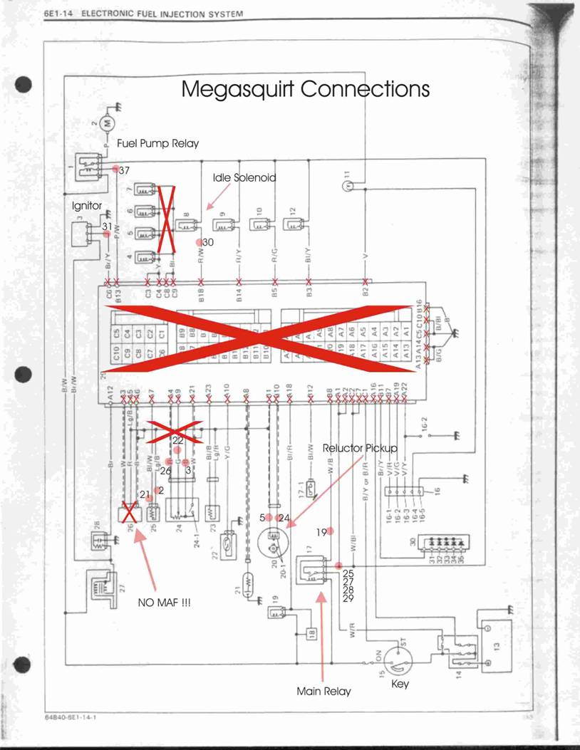
5. Connecting the Megasquirt to the Swift.
Before Starting, disconnect the negative wire from the battery. Then, unplug the stock ECU, you can leave the rest of the wiring plugged to the rest of the car, and even use it to connect your Megasquirt. I used my own wires but left the stock wiring in place and connected (not to the ECU), so I can get back to stock anytime. Leaving the stock wiring connected won’t hurt the MS functionality and will provide some necessary voltages to some relays and solenoids (fuel pump, main relay, idle solenoid) without having to route separate wires for them. Also, when routing wires to sensors, TPS, etc, use twisted wires for improved noise shielding. For reluctor pickup, use shielded wire.
Ground: A good ground is very important for the megasquirt. Do not use only one grounding point, but use three instead. I have used three ground wires. One for pins 7-8, one for pins 9-10 and another one for pin 11, may be 11-12 too because all pins from 1 to 19 are internally connected to ground. My grounding points are in the firewall, as close as possible to the MS. Ground wires should be no less than 18 gauge or 1mm2.
12 Volt: Take 12 volts from the white/blue wire coming out of the main relay. The relay is located in the fuse box next to the Battery, labeled FI. Use no less than 15 AWG or 1.5mm2.
Ground Loop: The main relay needs a ground loop to be closed in order to work. Connect Pin 19 of the MS to the white/black wire coming out of the main relay. 0.5mm2
Injectors: Make a new injector harness or modify the existing one in order to make two harnesses. One harness for cylinders 1-4, and the other one for cylinders 2-3. Feed one side of the injector coils with +12 volts from the main relay (white/blue) using 1.5mm2 wire and connect the other side of the injector coils to the MS, routing one 1mm2 wire from pin 32-33 to cylinders 1-4 and another 1mm2 wire from pins 34-35 to cylinders 2-3. See wiring diagram.
Fuel pump: the fuel pump relay is located next to the main FI relay. Connect pin 37 to the pink/white wire coming out of the FP relay. AWG22 or 0.35mm2.
Oxygen Sensor: I used a 4-wire narrow band sensor, fed with 12Volts from the FP relay. Take 12 volts from the pink wire at the FP relay. 1mm2 wire. Then connect the ground wire to chassis ground. 1mm2 wire.
+Signal wire: connect to pin 23 (0.35mm2).
-Signal wire: connect to pin 4 (0.35mm2)
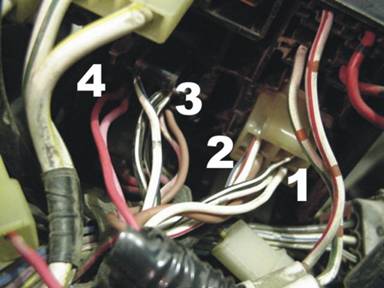
A close up of the fuse/relay box.
1-White wire soldered to black/white wire.
This white wire is the ground loop and connects
to pin 19.
2-Brown wire feeds the injectors and the Megasquirt
with 12 volts. It is soldered to white/blue wire.
3-Brown thin wire connected to pink/white wire at
the FP relay. This brown wire goes to pin 37.
4-Red wire connected to pink wire at the FP relay.
It feeds the O2 sensor with 12 volts.
Idle Solenoid: Connect pin 30 to the red/white wire at the idle solenoid. 0.5mm2

Idle solenoid:
The arrow shows the junction of
the red/white wire and a brown wire
connected to pin 30 of the MS.
Coolant temp sensor: use the stock one. Unplug it from the stock wiring and connect terminals to pins 21 and 2. Use twisted pair made of two 0.35mm2 wires.
Air temp sensor: Use a compatible sensor. I used a Volkswagen Golf GTi sensor, which matches perfectly to the stock coolant sensor. Connect to pins 1 and 20 using 0.35mm2 twisted pair.
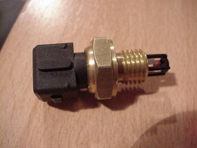
This is the air temp sensor I used. It belongs to
a VW Golf GTi and has the same response as the
stock coolant sensor. Note the fitting, it is a bosch
type fitting like the fuel injectors. Costed $5.
Throttle Position Sensor (TPS): Connect pin 26 to the red wire at the TPS, pin 22 to the yellow or green wire, and pin 3 to the black wire. The idle switch will remain unused. Use 3 twisted wires of 0.35mm2
Reluctor Pickup: there are two wires coming out of the distributor. Unplug them from the stock wiring and plug them to the MS using a shielded cable. Connect pin 24 to the red wire at the distributor using the central conductor, and pin 5 to the green wire using the shield. RG-174 coaxial cable is an excellent choice, but any shielded cable for audio will work.
Ignitor otput: The ignitor is right below the ignition coil, screwed to the same mounting bracket. It has 3 wires connected. Connect the ignitor output (pin 31 or pin 36) to the brown/yellow wire. Use 0.5mm2 wire.
Air pressure sensor (MAP sensor): The stock ECU is gone, and the evap canister will never work again. The intake manifold has a hose fitting for the evap canister that we can use to read the manifold pressure. Disconnect the rubber hose that goes to the canister and connect a rubber hose that goes to the megasquirt.

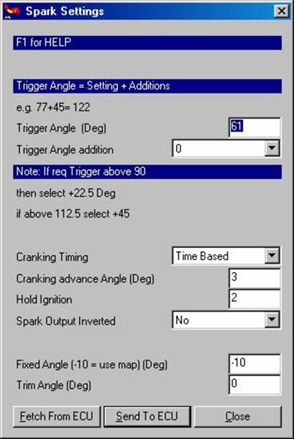
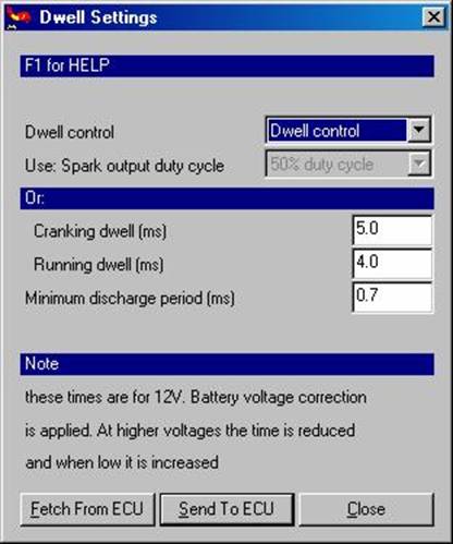
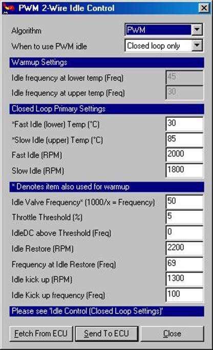
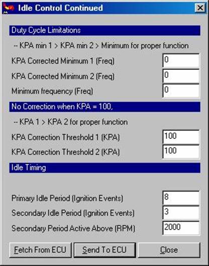
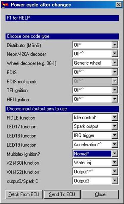
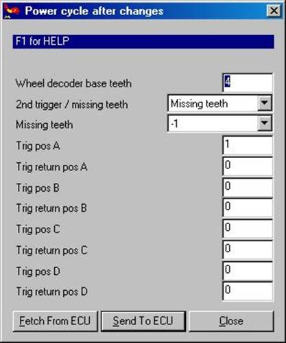
6. Set up.
Besides basic setup like number of fuel injectors, injection cycles, number of strokes and number of cylinders, It is necessary to set up the megasquirt to the new modifications, ie. Defining outputs and operation of the wheel decoder. You can download my MSQ from HERE and store it in your MS. Anyways, here are some screens with the most important ones.